The EthTSyn module is responsible for ensuring the collection and distribution of Ethernet synchronized time information. It interacts with StbM and provides all Ethernet-specific functions for StbM. The main functions of EthTSyn include measuring the delay between Ethernet messages and time synchronization before different time bases.
As shown in the figure, the EthTSyn module is located in the system service layer of the AUTOSAR architecture and depends on two modules, Ethif and StbM.
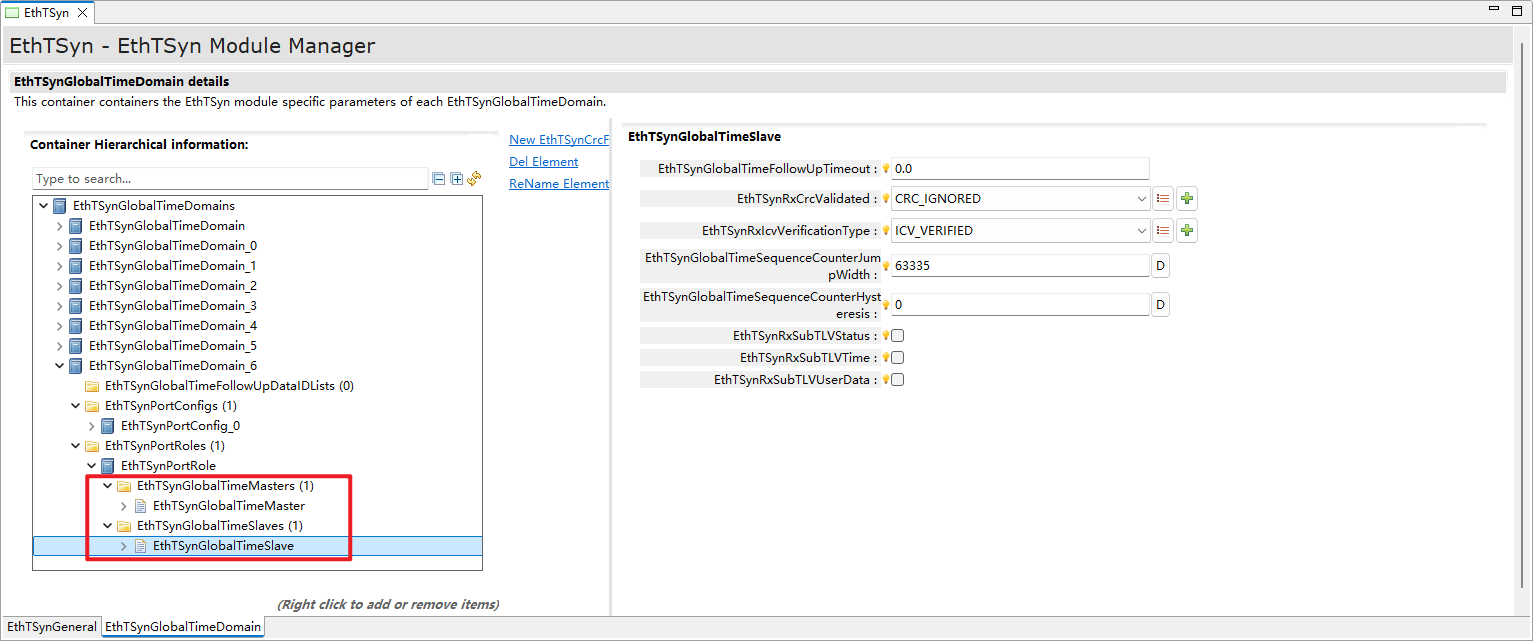
The working unit of EthTSyn is EthTSynPortConfig. Each EthTSynPortConfig obtains an EthIfController reference from its upper-layer container, EthTSynGlobalTimeDomain, and determines the partition of EthTSynPortConfig.
EthTSynGlobalTimeDomain and EthTSynPortConfig have a one-to-many relationship. Multiple EthTSynTimeDomain containers with the same EthTSynGlobalTimeDomainId are created to associate with different EthIfControllers and EthTSynPorts.
The memmap file is dynamic.There are ETHTSYN_START_SEC_CODE、ETHTSYN_START_SEC_CONST_8、ETHTSYN_START_SEC_CONFIG_DATA_32、ETHTSYN_START_SEC_CONFIG_DATA_PTR、ETHTSYN_START_SEC_CONFIG_DATA_UNSPECIFIED、ETHTSYN_START_SEC_VAR_CLEARED_8、ETHTSYN_START_SEC_VAR_CLEARED_16、ETHTSYN_START_SEC_VAR_CLEARED_64、ETHTSYN_START_SEC_VAR_CLEARED_BOOLEAN、ETHTSYN_START_SEC_VAR_CLEARED_PTR、ETHTSYN_START_SEC_VAR_CLEARED_UNSPECIFIED、VAR_CLEARED_GLOBAL_UNSPECIFIED、ETHTSYN_START_SEC_VAR_CLEARED_EcucPartition_C1P0_Trust_UNSPECIFIED.
EthTSyn adopts periodic time synchronization by default. The port acting as the master clock (TIME_MASTER) will send SYNC and FOLLOWUP messages cyclically at a configurable period. The global synchronization time is carried in the FOLLOWUP message. After receiving the SYNC message, the slave clock (TIME_SLAVE) will record the current time. After receiving the FOLLOWUP message, parse out the carried global synchronization time, and finally calculate the global time that needs to be updated locally for final synchronization.
In addition to periodic time synchronization, EthTSyn also supports immediate time synchronization. By calling the immediate time synchronization interface StbM_TriggerTimeTransmission of stbm from the upper-layer APP, the EthTSyn module will immediately trigger the sending of SYNC and Follow-Up messages.
The EthTSyn module supports measuring network delay. The measurement initiator will send a Pdelay_Req message. After receiving the request message, the receiver will restore the Pdelay_Response and Pdelay_Response_Followup messages. The requester can calculate the network delay. Note: Because the time synchronization of AUTOSAR conforms to 802.1AS, the time synchronization is required to be in p2p mode, that is, time synchronization and network delay are performed independently of each other.
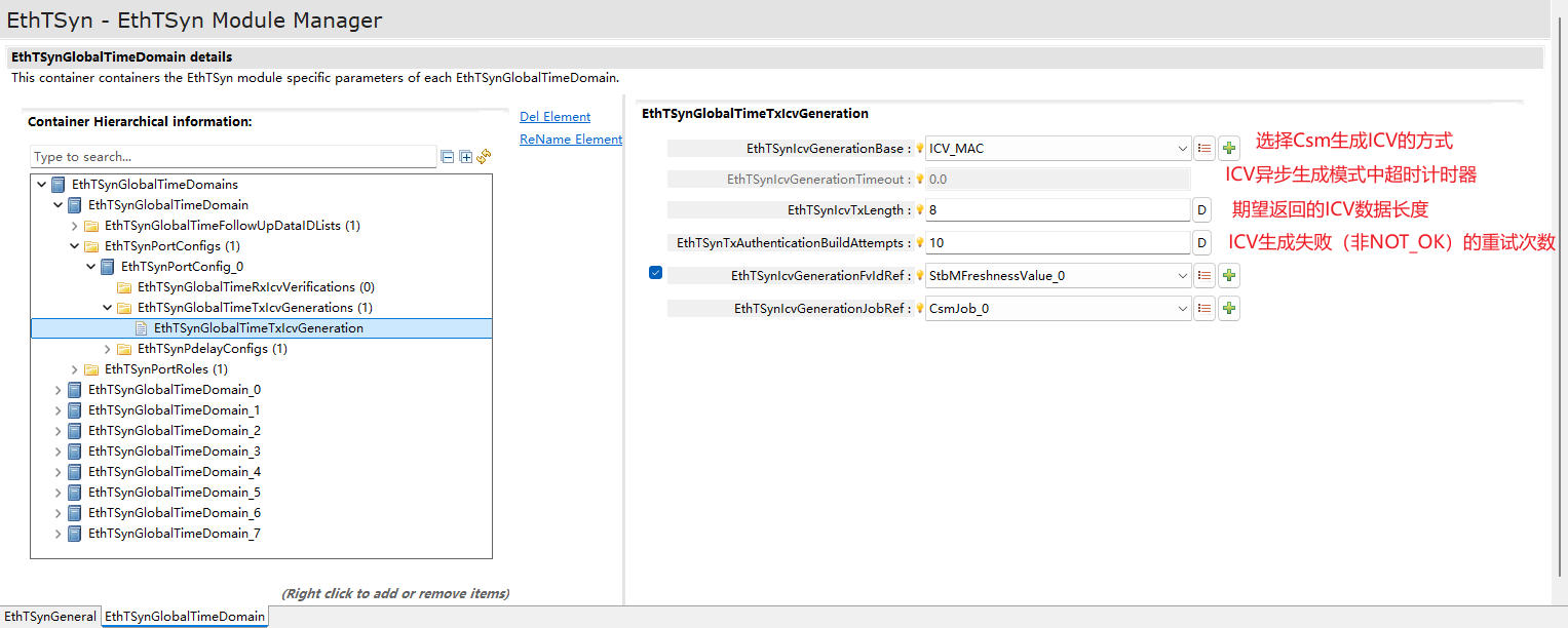
Security Time Synchronization is achieved by appending additional authentication information to Follow_Up messages. This authentication information is attached at the very end of Follow_Up messages in TLV format, following all Sub-TLVs. The security authentication information mainly consists of two parts: the Freshness Value (FV) and the Integrity Check Value (ICV). If the FV acquisition fails or the ICV generation/verification fails during the process of obtaining the FV and generating/verifying the ICV, the processing will be skipped, and corresponding security events will be reported.
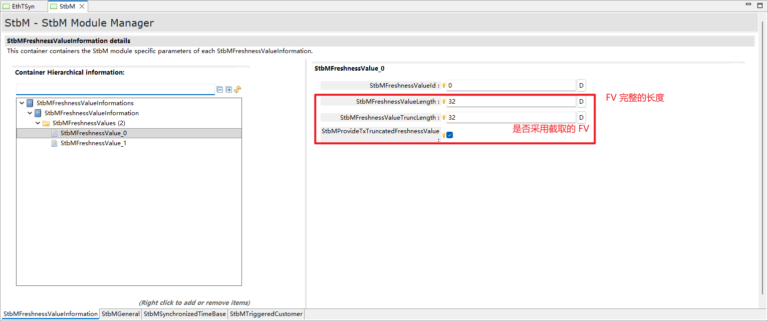
The FV points to a monotonically increasing counting mechanism used to ensure the freshness of the time base, guaranteeing that the received time information does not regress in chronological order to prevent the replay of old time information. This monotonic mechanism can be implemented through an independent Message Counter (Freshness Counter) or via a Freshness Timestamp.
FV 在StbM中进行管理和维护:
FV is managed and maintained within the StbM:
When transmitting a Follow_Up message, the FV corresponding to the current Timebase is obtained from the StbM via the specified API based on the configuration and attached to the Follow_Up message.
When the receiver processes the incoming Follow_Up message, it obtains the FV corresponding to the current Timebase from the StbM and uses it to construct the ICV generation message for integrity verification.
If FV acquisition fails, the ICV calculation and attachment process is skipped, and a flag is written into the Follow_Up message to indicate that the message does not possess authentication capability.
ICV refers to the calculation result of a cryptographic function, used to ensure that unauthorized modifications to the message can be detected. This cryptographic function can employ any cryptographic primitive and be implemented in combination with a corresponding cryptographic key.
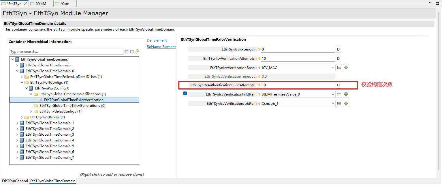
The use of ICV on the receiver side is optional. To achieve greater flexibility across multiple time observation units, relevant configurations determine how messages with ICV are processed.
如果接收端不启用 ICV 校验,则可能仅使用接收到的数值,而不对 ICV 本身进行验证。
If the receiver does not enable ICV verification, it may only use the received values without verifying the ICV itself.
If the receiving end enables the ICV option, a side effect must be considered: Since Pdelay messages do not contain any TLVs, the associated timestamps cannot be protected by ICV. If the application uses ICV in Follow_Up messages while also employing non-static Pdelay, then when calculating the corresponding Time Base value, it is unavoidable to mix the unprotected Pdelay timestamps with the ICV-protected Follow_Up timestamps.
ICV 的计算和验证算法由 Csm 模块负责实现:
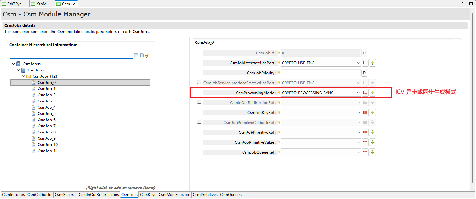
The ICV calculation and verification algorithms are implemented by the Csm module:
When the transmitter sends a Follow_Up message, after obtaining the FV, it constructs the data for ICV generation and calls the API provided by the Csm to calculate the ICV, attaching it to the authentication TLV of the Follow_Up message.
When the receiver processes the received Follow_Up message, it extracts the ICV; similarly, it must first obtain the FV and construct the data for ICV verification, then call the API provided by the Csm to verify the correctness of the ICV.
The range of the constructed data starts from a beginning byte of the Follow_Up message to the end byte of the FV field, excluding the ICV field itself.
If the configuration selects the use of a truncated FV, the full FV is used when constructing the verification data, but the truncated FV is filled into the actually transmitted Follow_Up message.
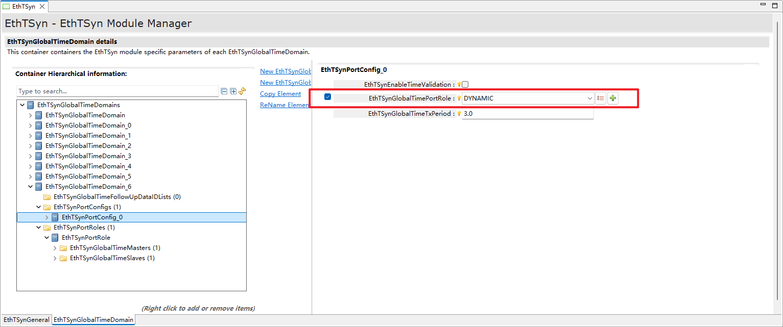
时间主节点和时间从节点的动态端口配置(Dynamic Port Configuration for Time Master and Time Slave Nodes)
In the EthTSyn module, to ensure high system availability by introducing backup clock sources into the time synchronization topology, a dynamic port role configuration function has been implemented. This allows the roles of time master nodes and time slave nodes to change dynamically during runtime.
Under normal conditions, the backup clock source remains inactive. When the primary clock source fails or becomes unavailable, the backup clock source can be activated to take over the responsibilities of time synchronization. Additionally, gateway nodes can dynamically switch their time synchronization roles based on network conditions to adapt to different network topologies and requirements.
For example, when the interface of a gateway node is configured as the DYNAMIC type, and the primary clock source sends out SYNC and Follow_Up messages, the DYNAMIC port that receives the synchronization messages will operate as a SLAVE type to receive time synchronization messages. All other DYNAMIC ports will function as MASTER type ports to forward SYNC and Follow_Up messages outward.
When the primary clock source becomes unavailable, all DYNAMIC ports that have transitioned to SLAVE or MASTER roles will revert to the DYNAMIC type, awaiting re-activation by the backup clock source to establish a new time synchronization topology.
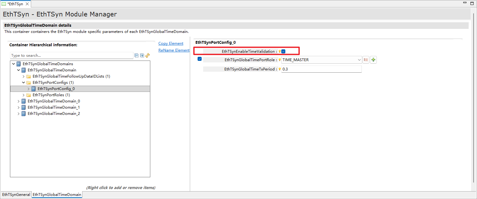
The Time Validation feature is introduced to enable the time synchronization system to detect time deviations between master and slave nodes during operation, identify time synchronization degradation or anomalies, and determine from a system-wide perspective whether a trusted and consistent time base has been established.
TimeSync 模块需要能够采集时间同步状态信息,并将这些信息提供给应用(即Validator SWC),以支持 Time Validation 功能的实现。Time Slave、Time Master 以及 Time Gateway 会从相应的 TimeSync 模块中收集时间同步过程的相关信息,例如:基于其本地的全局时间实例(通过使用 SyncLocal Time Tuple)、时间同步报文的接收时间戳、时间同步报文中的全局时间信息等,来计算时间偏差和其他相关指标。
The TimeSync module must be able to collect time synchronization status information and provide this information to the application (i.e., Validator SWC) to support the implementation of the Time Validation function. Time Slave, Time Master, and Time Gateway will collect information related to the time synchronization process from the corresponding TimeSync modules—for example, based on their local global time instances (by using SyncLocal Time Tuple), reception timestamps of time synchronization messages, and global time information within time synchronization messages—to calculate time deviations and other relevant metrics.
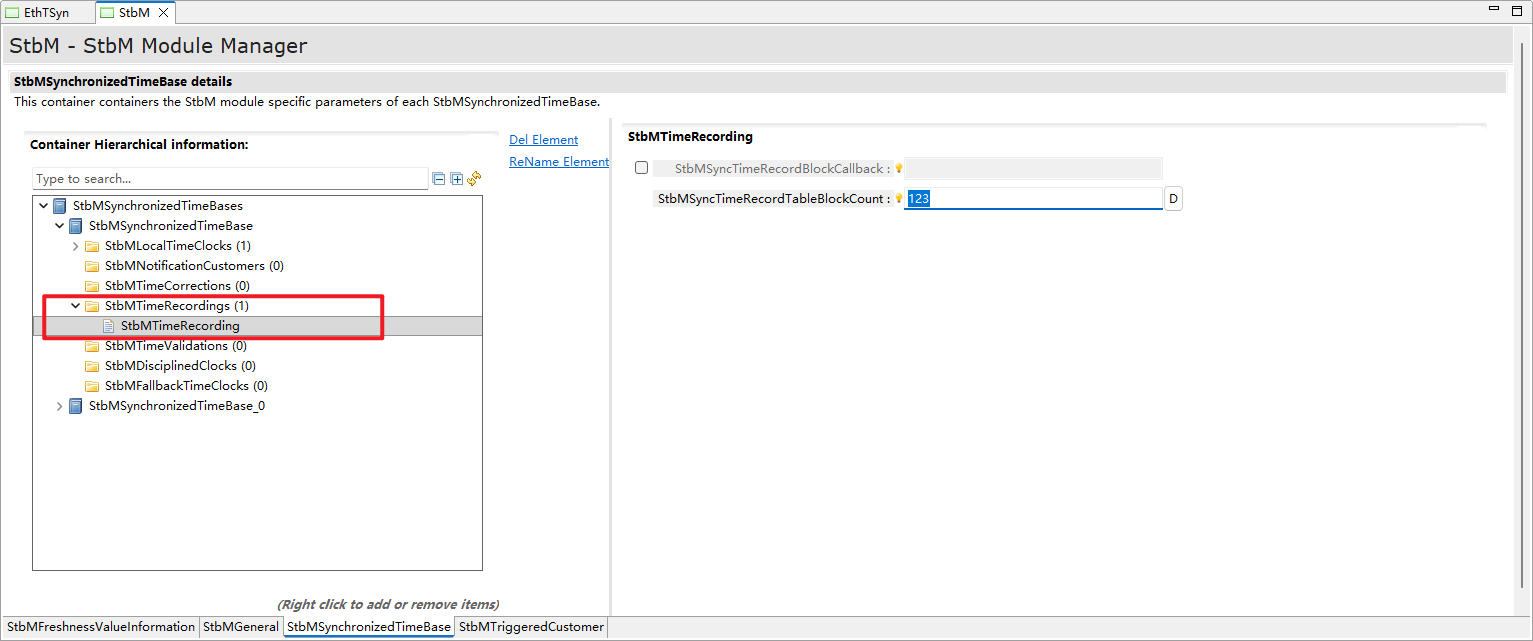
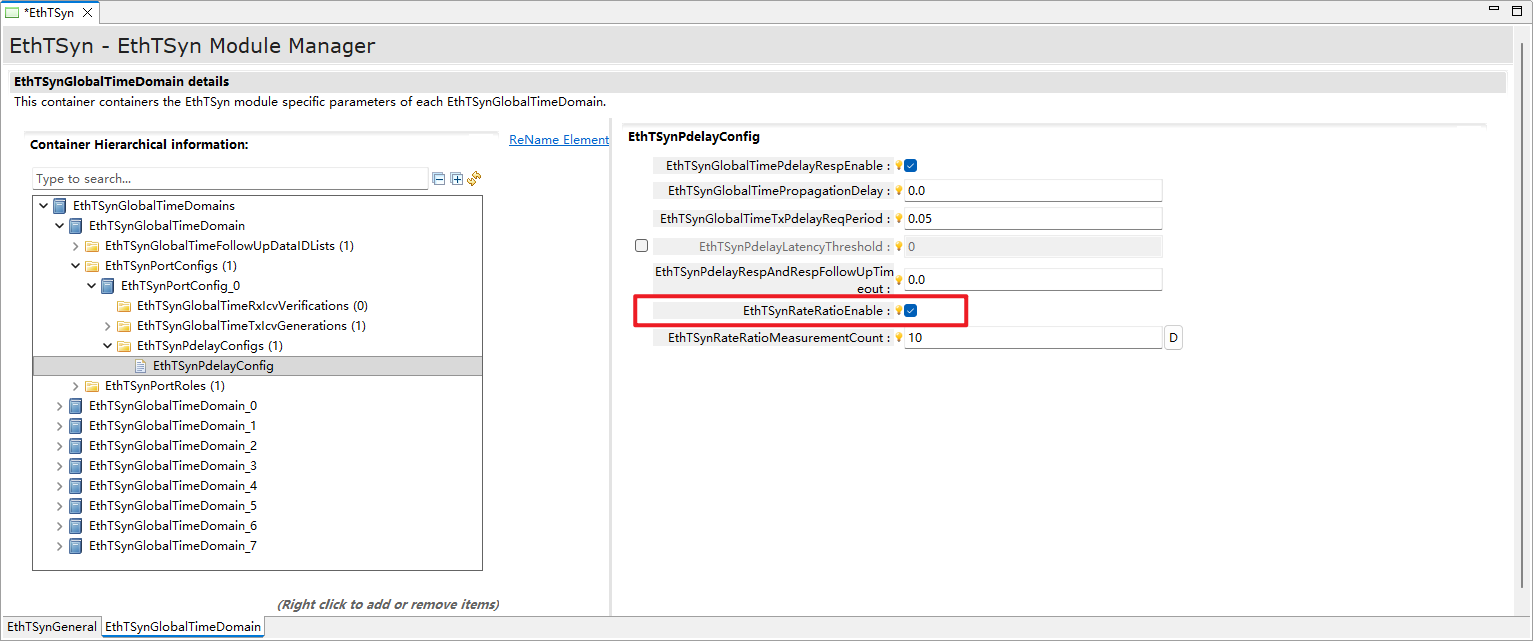
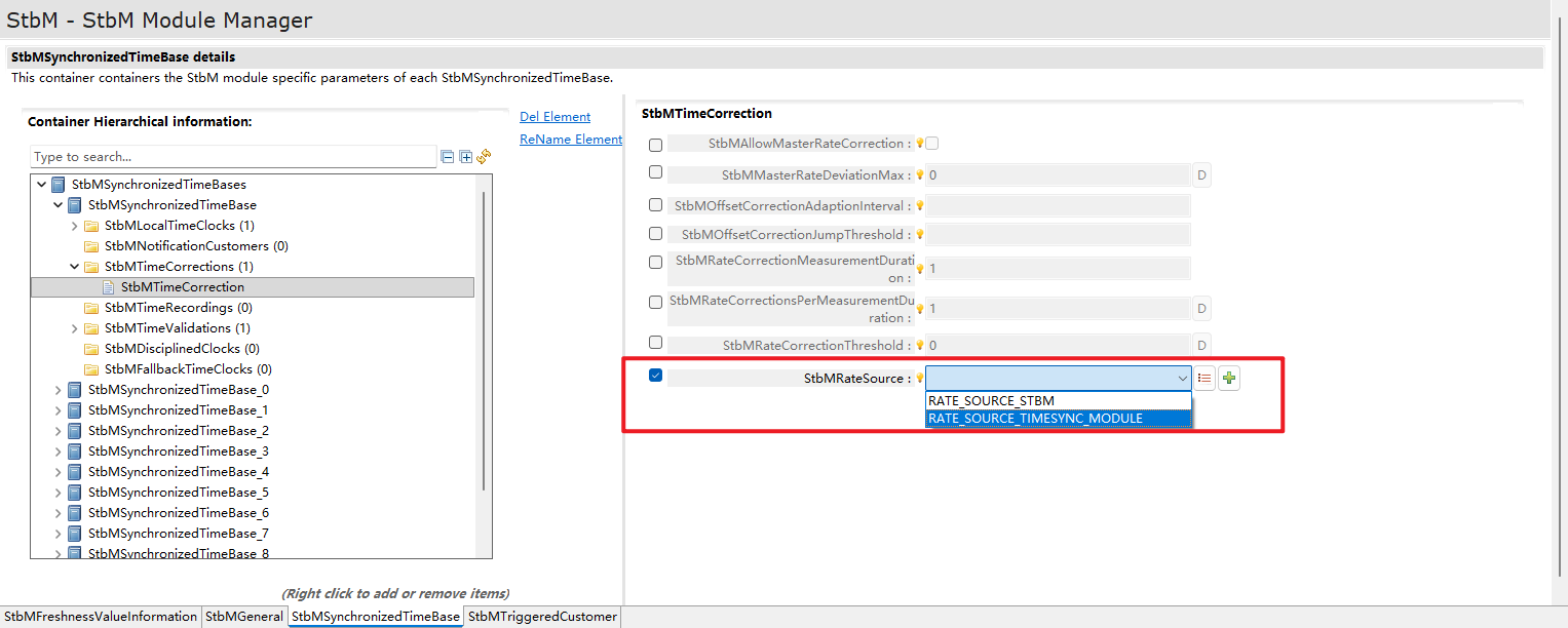
Clock Rate Ratio refers to the frequency relationship between two clocks. By calculating and adjusting the rate ratio, it ensures that the slave clock can operate at the same rate as the master clock, thereby achieving more precise time synchronization.
速录比的计算可以根据配置决定是由 StbM 进行计算,还是由 TimeSync 模块进行计算。
The calculation of the rate ratio can be configured to be performed either by the StbM (Synchronization Time Base Manager) or by the TimeSync module, depending on the system configuration.
实现EthTSyn模块全部外部接口的声明,以及配置文件中全局变量的声明(Implements the declaration of all external interfaces of the EthTSyn module and the declaration of global variables in the configuration file)
EthTSyn_Types.h
实现EthTSyn模块全部数据类型的声明(Implements the declaration of all data types of the EthTSyn module)
EthTSyn.c
作为EthTSyn模块的核心文件,实现EthTSyn模块全部对外接口,以及实现EthTSyn模块功能所必须的local函数,local宏定义,local变量定义(As the core file of the EthTSyn module, it implements all external interfaces of the EthTSyn module, as well as the local functions, local macro definitions, and local variable definitions necessary for implementing the functions of the EthTSyn module)
This service makes a CRC8 calculation with the Polynomial 0x2F on Crc_Length.
Det_ReportError
Det.h
Service to report development errors.
EthIf_EnableEgressTimeStamp
EthIf.h
Activates egress time stamping on a dedicated message object. Some HW does store once the egress time stamp marker and some HW needs it
always before transmission. There will be no “disable” functionality, due to the fact, that the message type is always “time stamped” by
network design.
EthIf_GetEgressTimeStamp
EthIf.h
Reads back the egress time stamp on a dedicated message object. It must be called within the TxConfirmation() function.
EthIf_GetIngressTimeStamp
EthIf.h
Reads back the ingress time stamp on a dedicated message object. It must be called within the RxIndication() function.
EthIf_ProvideTxBuffer
EthIf.h
Provides access to a transmit buffer of the specified Ethernet controller.
EthIf_Transmit
EthIf.h
Triggers transmission of a previously filled transmit buffer
StbM_BusSetGlobalTime
StbM.h
Allows the Time Base Provider Modules to forward the Rx Time Tuple to the StbM.
StbM_GetCurrentTime
StbM.h
Returns a time tuple (Local time, Global time and Timebase status) and user data details Note: This API shall be called with
locked interrupts / within an Exclusive Area to prevent interruption (i.e., the risk that the time stamp is outdated on return of the
function call).
StbM_GetCurrentVirtualLocalTime
StbM.h
Returns the Virtual Local Time of the referenced Time Base.
StbM_GetTimeBaseStatus
StbM.h
Returns detailed status information for a Synchronized (or Pure Local) Time Base and, if called for an Offset Time Base, for the Offset Time
Base and the underlying Synchronized Time Base.
StbM_GetTimeBaseUpdateCounter
StbM.h
Allows the Timesync Modules to detect, whether a Time Base should be transmitted immediately in the subsequent <Bus>TSyn_MainFunction() cycle.
There are two ways to implement time synchronization, one is implemented through hardware timestamp, and the other is implemented through software timestamp. The hardware timestamp implementation method is to collect timestamps through hardware.
Hardware timestamp means that the interface for obtaining time uses the timestamp function of Ethernet hardware, that is, the timestamp is obtained by calling the interface of EthIf. For the master time node, because time synchronization has high requirements for accuracy, and because there is a time delay from calling the sending interface to the message actually being sent from the network port, if the hardware timestamp method is not adopted, it is impossible to obtain a more accurate message exit time, and thus it is impossible to calculate an accurate preciseOriginalTime, resulting in a decrease in the accuracy of synchronization after the slave receives the FollowUp message.
同理,对于slave来说,如果不是用硬件时间戳,无法拿到准确的报文入口时间。
Similarly, for the slave, if hardware timestamp is not used, an accurate message entry time cannot be obtained.
下面是配置支持硬件时间戳的基本步骤:
The following are the basic steps to configure support for hardware timestamp:
As shown in the figure above, in EthTSynGeneral, enable support for hardware timestamp, that is, check EthTSynHardWareTimestampSupport. Other common configuration items, such as period.
domain配置的图片 (Picture of Domain Configuration)
StbM时钟源配置的图片 (Picture of StbM Clock Source Configuration)
A time domain can be configured with multiple Ports. EthTSynGlobalTimeHardware refers to which Ethernet Port the clock source configured for the StbM time base associated with the current time domain comes from. EthTSynGlobalTimeHardware takes effect if and only if the time base (EthTSynSchronizedTimeBaseRef) configured in the time domain is associated with the Ethernet clock in StbMLocalTimeClock.
Configure the Port under the time domain, such as the time synchronization role EthTSynGlobalTimePortRole, the sending interval of SYNC and Follow-Up messages EthTSynGlobalTimeDebounceTime, and the EthIfController associated with the Port.
Configure the relevant parameters of the master time node under the time domain, such as the recovery time from immediate synchronization to periodic synchronization EthTSynCyclicMsgResumeTime, the message sending period EthTSynGlobalTimeTxPeriod, etc.
In addition to the above configuration, in order to support hardware timestamp, the hardware timestamp function of Mcal also needs to be enabled. At the same time, register the interfaces related to hardware timestamp to the EthIf layer, as shown in the figure above. And register the connection status callback of EthTSyn to the EthIf layer, as shown in the figure below.
In addition, if you need to activate the time synchronization Master, you first need to call the interface StbM_SetGlobalTime of StbM in the application layer to set the global time of the time base in this time domain, and call EthTSyn_SetTransmissionMode to activate the transmission state.
 开源小满EasyXMen